
VIGO PHOTONICS · SMART TAIWAN
AMIS8140-01 optically immersed IR detection module
AMIS8140-01
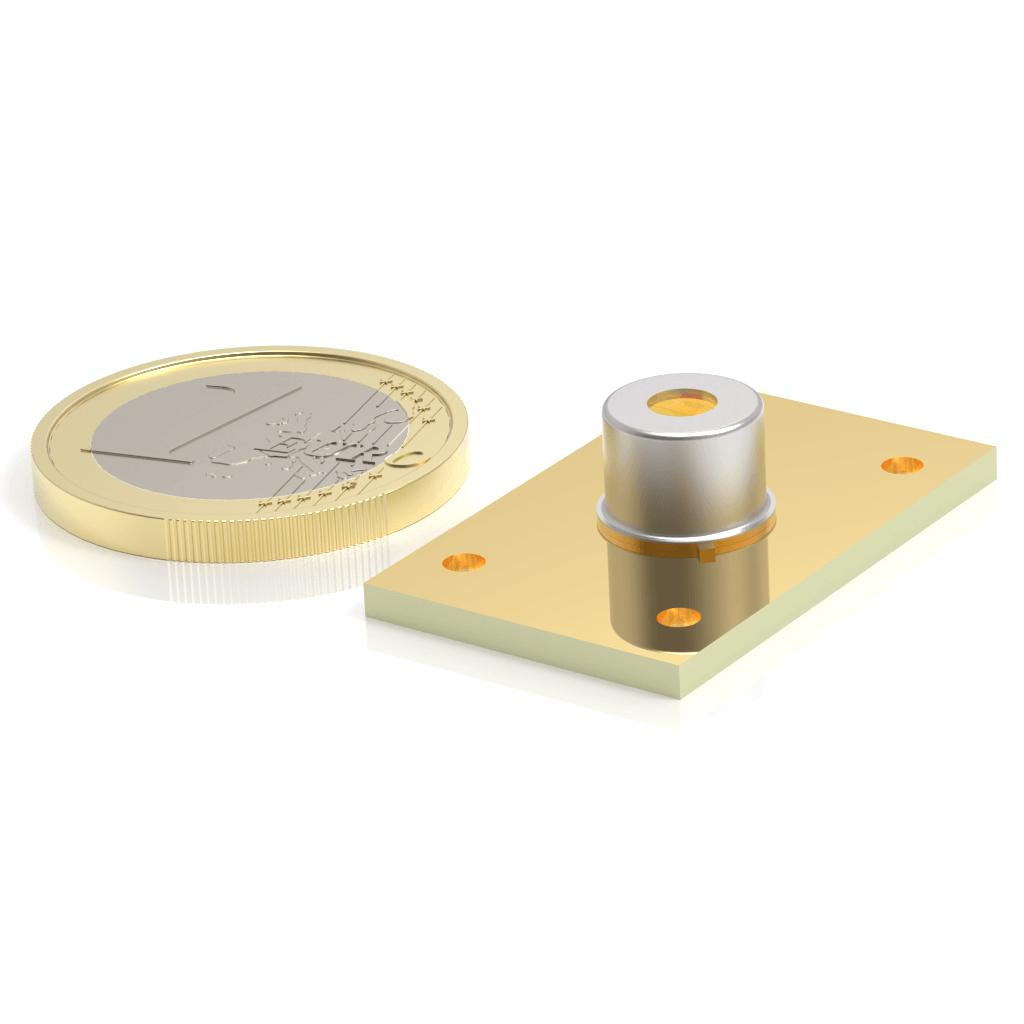
An optically immersed InAsSb module integrating a differential amplifier and temperature controller for measurements extending into the LWIR. Match optical area, acceptance angle and responsivity at the operating wavelength to the optical design.
Specifications and configuration
| Material / detection | InAsSb / photovoltaic |
|---|---|
| Active / optical area | 1 × 1 mm (optical area, immersed) |
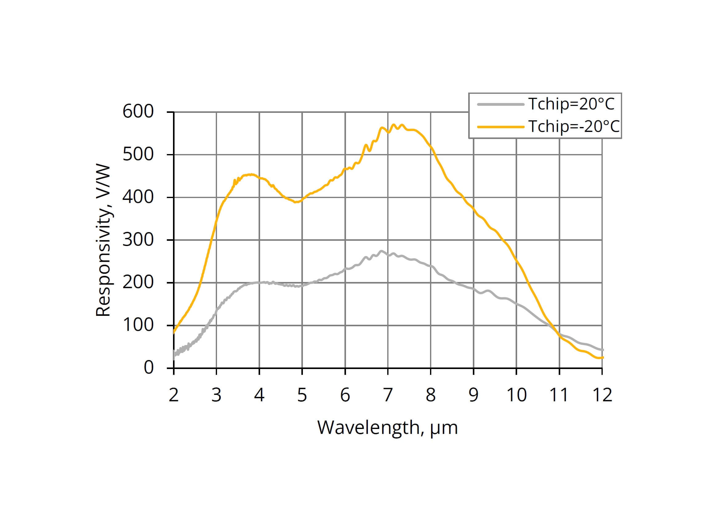
| Typical spectral range | 1.9–11.0 μm (Tchip −20°C) |
| Peak wavelength | 7.4 μm (typ.) |
| Typical responsivity | 550 V/W (λpeak) |
| Typical D* | 2.4 × 10⁹ cm·Hz½/W (λpeak, 1 kHz) |
| Typical bandwidth | DC–3.0 MHz (Rload 50 Ω) |
| Supply | 3.3 V |
| Signal output | Differential analogue output |
| Cooling / temperature control | 1TE; integrated controller |
| Outline / interface | 30 × 19 × 10 mm; board-to-board connector |
Tamb = 20°C; Tchip = −20°C; +3.3 V; Rload = 1 MΩ to ground unless noted; fhi at Rload = 50 Ω.
Typical values are not guaranteed limits. Refer to the original English datasheet for full test conditions, minimum / maximum values and operating limits. D* figures measured at different frequencies are not directly comparable.
Manufacturer spectral response
Temperature and readout conditions
| Tchip | Spectral range (10%) | Peak responsivity | High cut-off frequency |
|---|---|---|---|
| −20°C | 1.9–11.0 μm | 550 V/W | 3.0 MHz |
| 20°C | 1.9–11.5 μm | 270 V/W | 1.0 MHz |
Tamb = 20°C; high cut-off frequency measured at Rload = 50 Ω. Temperature control and heatsinking determine the achievable operating point.
Selection and integration considerations
- Provide a heatsink and thermal interface; setpoint capability depends on ambient temperature, supply and thermal design.
- Match the differential analogue output to the receiver / ADC, load and input range. It is not a USB or digital output interface.
- Specify wavelength, beam size, optical power and modulation frequency rather than selecting by cut-off or detectivity alone.
From module to measurement system
- Source / measurement target
- Filters and optical coupling
- IR detection module
- Differential receiver / ADC
- Signal processing and calibration
The module provides part of the sensing and analogue chain. A complete measurement also needs optics, power, readout and calibration.
Original English documents and resources
V2.0 · 2026-07-08
Start with your measurement requirements
Share the model or application, wavelength, signal bandwidth, quantity and desired schedule. Unknown items can be discussed during selection.
Submit a VIGO inquiry